DE
DE CZ
CZ HU
HU PL
PL SI
SI
Optimized components and individual solutions for dust collector systems
Dust filters are used in many different industries – they remove dust and dirt from the exhaust air. In order to clean the filters, they are blown off shock-like by a strong compressed air pulse. For this you need pulse valves.
What is dust actually?
Dust is defined as the smallest, partially invisible, solid particles that can float in the air. Dust can simply be annoying and unpleasant (dirt, wear), but also life-threatening (carcinogenic, explosive). Especially fine dust poses high health risks.
Anthropogenic dusts endanger health
In most cases, anthropogenic dusts are fine dusts that can be hazardous to health because they can contain substances such as lead or mercury. In addition, hydrocarbons or sulfur compounds can settle on their surfaces.
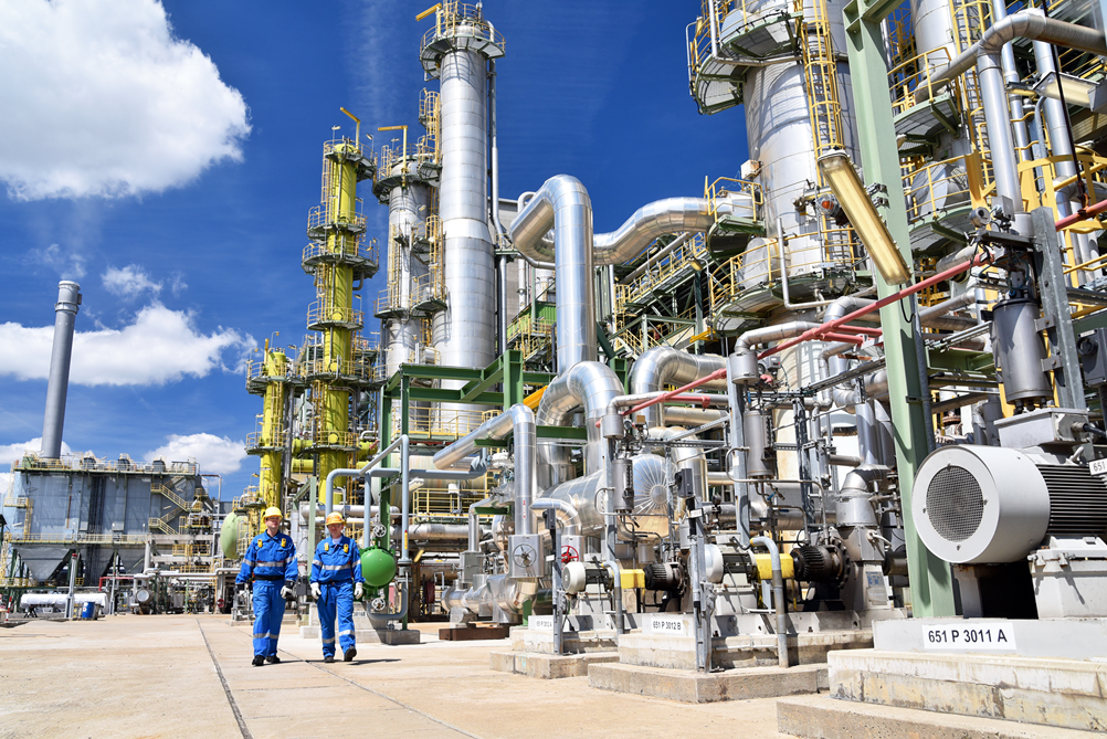
For this reason, especially in the industrial sector, attempts are made to remove dust from the air directly at the source.
There are many sources of dust in industry: in the production of cement, tablets, fertilizers, wood pellets and asphalt, in sawmills, bakeries, foundries and grain mills, in furniture production, waste incineration, textile processing, powder coating and blasting technology, in recycling, welding, soldering and flame cutting, in grinding processes, in fossil power generation, in ore mining and many more.
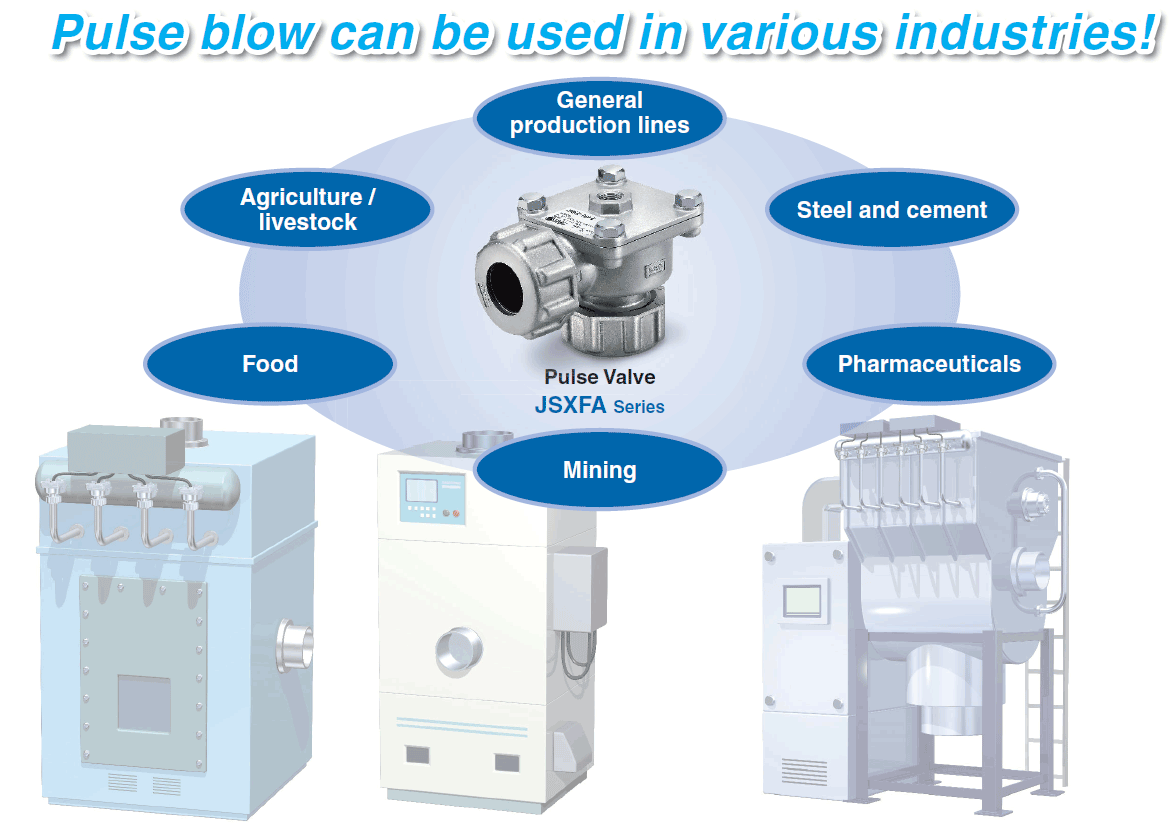
Jet pulse cleaning with the JSXFA pulse valve
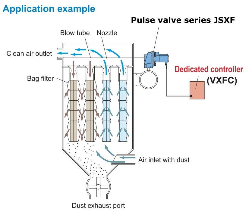 Whether in central dust collectors or local dust extraction systems – at some point every filter element is saturated. Hardly any of the air loaded with dust can be sucked in anymore and reach the external environment again as cleaned air.
The filters are cleaned by short, shock-like blow-offs in the opposite direction. A short burst of compressed air pushes the filter cake off the filter material. By inflating the filter bag, any additional encrusted dirt can flake off.
A central element in the cleaning of the filters is the pulse valve. Its task is to provide the largest possible amount of air in the shortest possible time to blow off the filter cake by a shock pulse. The decisive factor is therefore the pressure pulse as the result of air pressure (impact force) and compressed air volume.
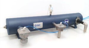
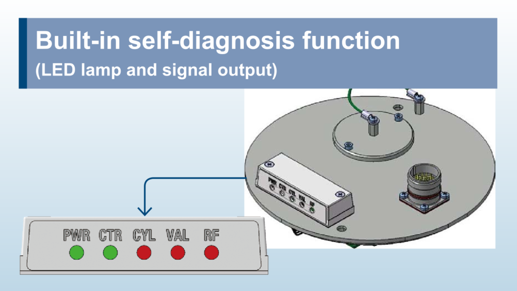
Advantages of the JSXFA Series Pulse Valve
In addition to impulse valves of the JSXFA series, SMC also provides electrical (VXF2 series) and pneumatic (VXFA2 series) pulse valves.

The valves of the new JSXFA series have numerous advantages:
- Higher flow rate of up to 50 percent compared to conventional pulse valves thanks to improved geometry.
- Together with its faster response, it generates about 15 percent higher pressure pulse.
- At the same time, the large “pressure release hole” promotes faster closing and reduces the total air consumption of the blowing pulse by around 35 percent.
- Extremely long service life of at least 10 million cycles due to springless design and special high-strength elastomer diaphragm. With one cleaning per minute, a failure would therefore be expected after approx. 19 years – but since the cleaning intervals are two to ten minutes, the service life is even longer.
- Extremely service-friendly: easier installation and faster maintenance thanks to springless diaphragm (even when installed).
- Can be used for a wide temperature range (-40 to +60°C).
- A reduction of response time by about 45 percent when switching off.


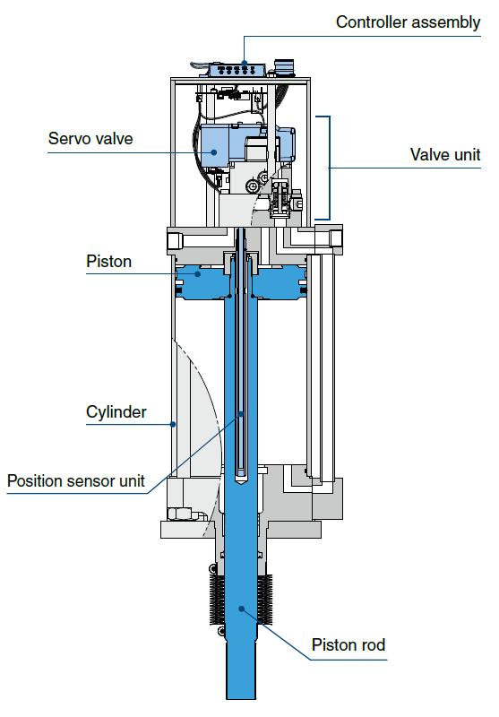

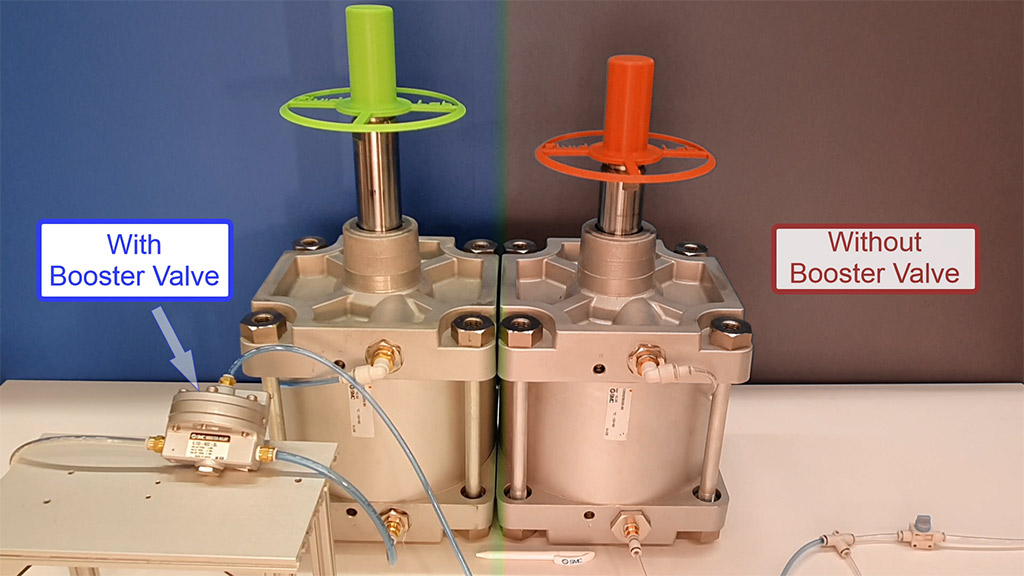
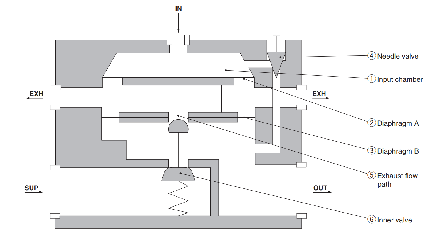
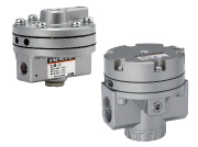 Features of Booster Valves
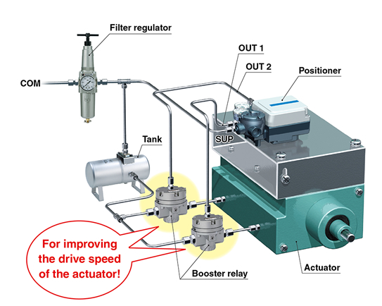 Range of applications of booster relays
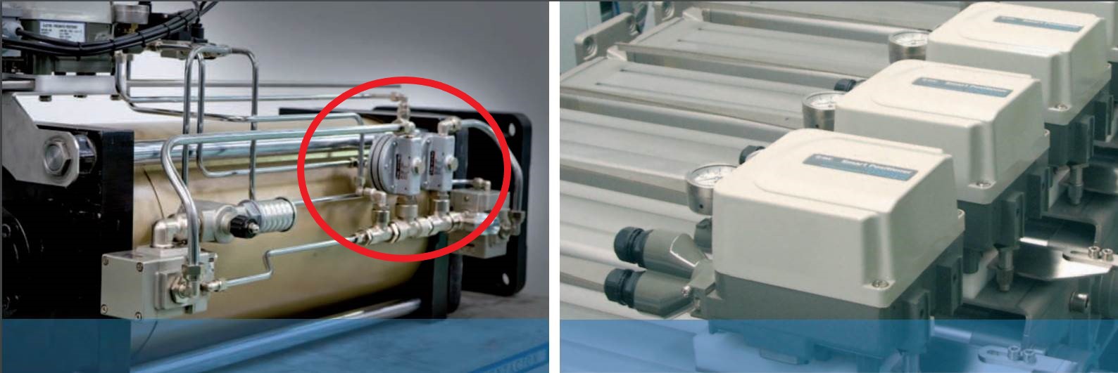

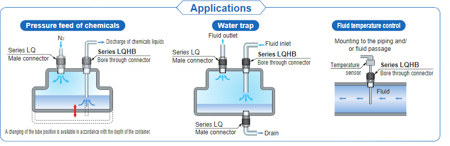


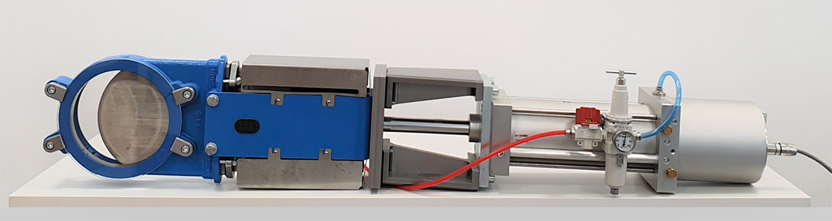
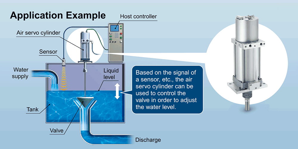
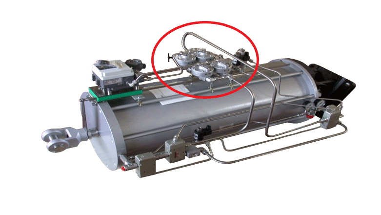
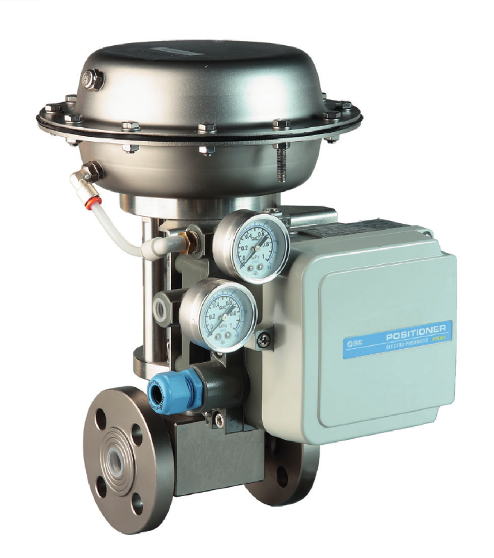 There are valves in almost all areas of industries and they usually have to be operated and automated pneumatically. Industrial valves control and regulate the flow of gases, steam or liquids in pipelines. If necessary, the valves also shut off the flow.
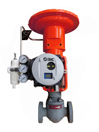
 We offer you all-in-one solutions for your valve automation and develop individual solutions for your applications according to your wishes and requirements with high-quality SMC products.